CLPC LC (Closed Loop Positioning Control)
Provides Accurate, High Cycle, Clutch Brake Positioning Control
Continuously Correcting for Stop In Position Accuracy
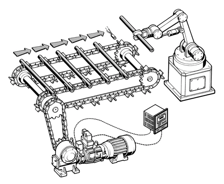
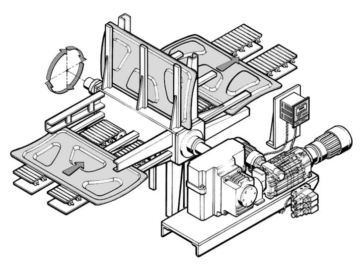
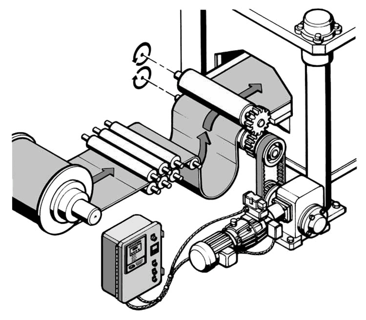
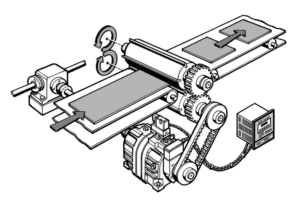
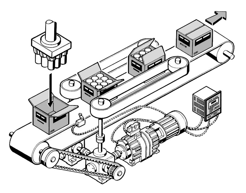
The CLPC is used to control a Posidyne Clutch Brake on cycling applications where very accurate stopping position is critical. Often when using a clutch brake in this application a limit switch or PLC is used to set the stop position. Because the Posidyne Clutch Brake with Oil Shear Technology is very consistent running steady, this works fairly well. However, as with any clutch brake unit, changes in temperature, cold start to hot run and other variables cause the stopping to be shorter or longer, thereby overshooting or undershooting the desired position. The CLPC corrects for this.
How they work.
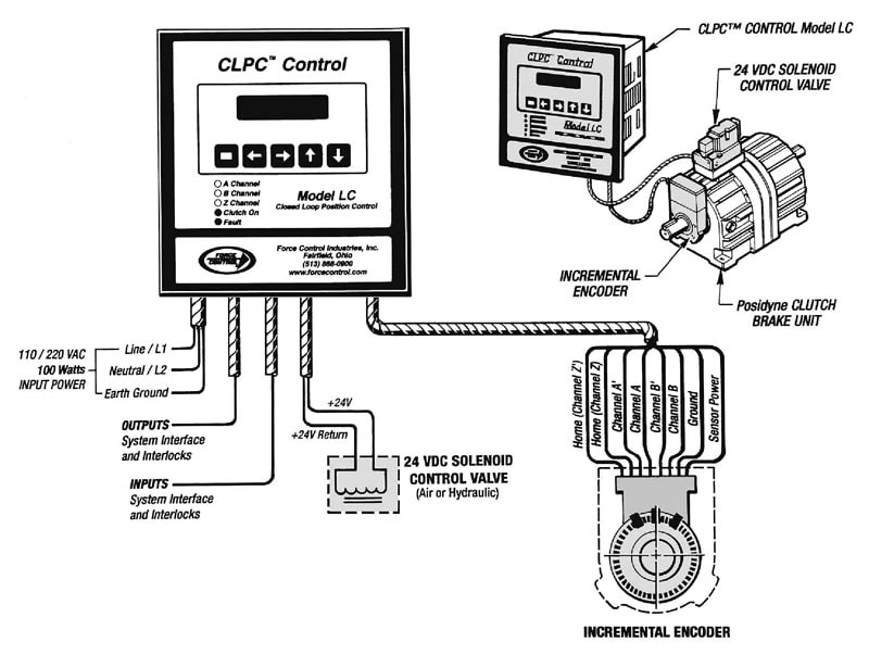
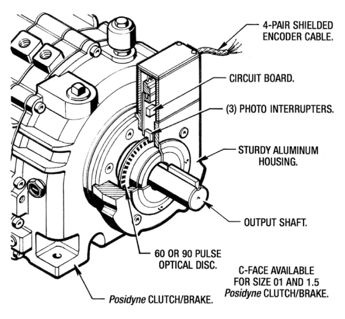
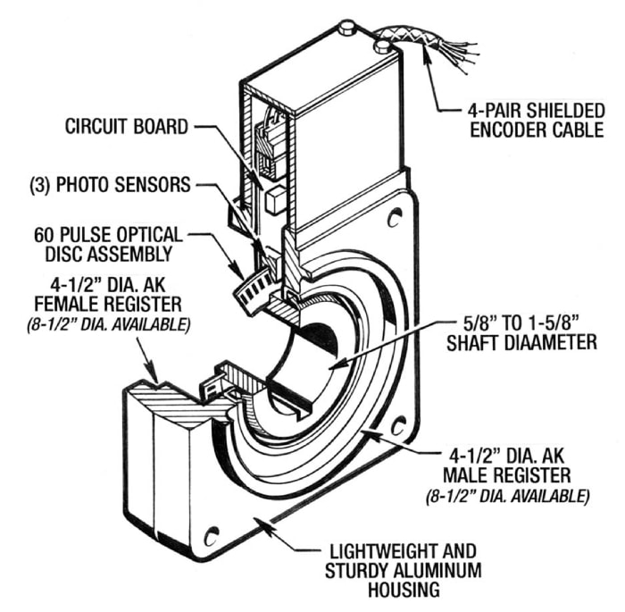
The original CLPC was designed to control high cycle applications where the scan time of PLC’s was too slow for accurate positioning. It consists of the CLPC control unit and a position encoder mounted on the clutch brake output shaft. The optical encoder counts pulses back to the CLPC control. The control is then programmed via push buttons on the face of the control to index (when given a start signal) the desired number of pulses for a complete index. Because a brake will not stop the drive instantly the brake must be engaged before the stop position allowing time for the drive to decelerate to stop. This is called the “trigger point”. When first starting the drive the index distance is programmed into the control and the trigger point is set automatically. As the drive is indexed, if the stop is out of position, the trigger point automatically adjusts until the stop is in location. This typically works on a 5 index algorithm to avoid hunting. When the correct number of pulses is reached (the trigger point) the control will signal the brake to engage and release the clutch. The stop position can be adjusted by using the manual adjust setting to adjust the stop position 1 pulse at a time to the desired position. This then becomes the stop or home position. When the brake signal is received and the brake is engaged it will decal to stop within so many pulses. In operation any variation in stopping due to temperature change or load change, or torque change will cause the stop to be out of position. The trigger point (count when the brake is signaled to engage) will then be adjusted to compensate for the error. This is done on a 5 count algorithm to avoid “hunting”. The result is the trigger point continually adjust itself to maintain an accurate stopping position.
CLPC Features, Functions and Capabilities
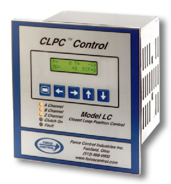
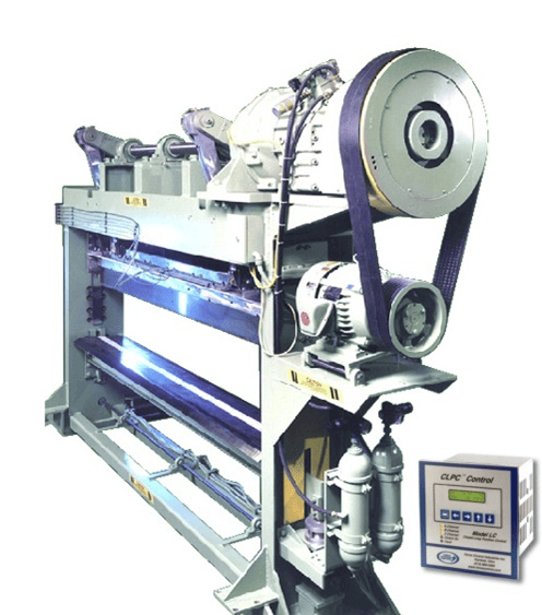
The basic CLPC Control Model LC is designed to operate a standard Posidyne Clutch/Brake in an indexing application. The CLPC-LC is programmed for the desired index distance (encoder counts). The CLPC-LC will energize the clutch valve until the trigger point, de-energize the valve and stop in position. The trigger point is self compensating to actuate the brake at the proper time to consistently stop in position and will float as conditions change. The CLPC Control Model LC is a single direction single clutch drive control.
The CLPC Control Model LC has numerous features such as:
- Universal Supply Input – 85-264 VAC, 47-63 Hz
- Interface – All functions adjustable with a simple menu through a display panel.
- Program Lockout – via external cold contact.
- Eleven Internally Tested Functions – Error Codes with descriptions displayed to identify Faults.
- Compact Design – Door Mount or Panel Mount.
- Always Ready – No calibration required.
- Stall Detection – Detects a jam (no rotation of the encoder) before reaching the desired stop position and disengages the clutch.
- Watch Dog Timer – Adjustable (100 milliseconds to 1 minute) timer which will disengage the clutch if timed out before reaching the desired stop position. Used to protect against jams which may stop or slow down the drive.
- Encoder Resolution Settings – X1, X2 and X4.
- Manual Adjustment – Allows a positive or negative adjustment from the home sensor position. Used to align the machine position with the home sensor
- Emergency/Fault Stop – Abort Input allows the control to react to an external request to stop the index or prevent any further indexes from occurring.
- In Position Output – An output to indicate when the drive has reached position. A plus or minus count can be set as an allowable in position window.
- Optional (MIP/PLS) – Multiple Indexing Parameter groups – Capable of storing up to 16 different groups (Index Distances). Programmable Limit Switch—Capable of 4 Programmable Outputs based on position


